


Design a Raspberry Pi enclosure
Mix.install([{:smith, "~> 0.4.0"}, {:kino, "~> 0.19.0"}])The design
We are building a desktop enclosure for a Raspberry Pi 5 and its Active Cooler. The board rides on a sliding tray. A quarter-turn cam locks the tray into the chassis. Above the cooler, a curved duct leads to a removable grille. The lid, duct, and grille lift away together for maintenance.
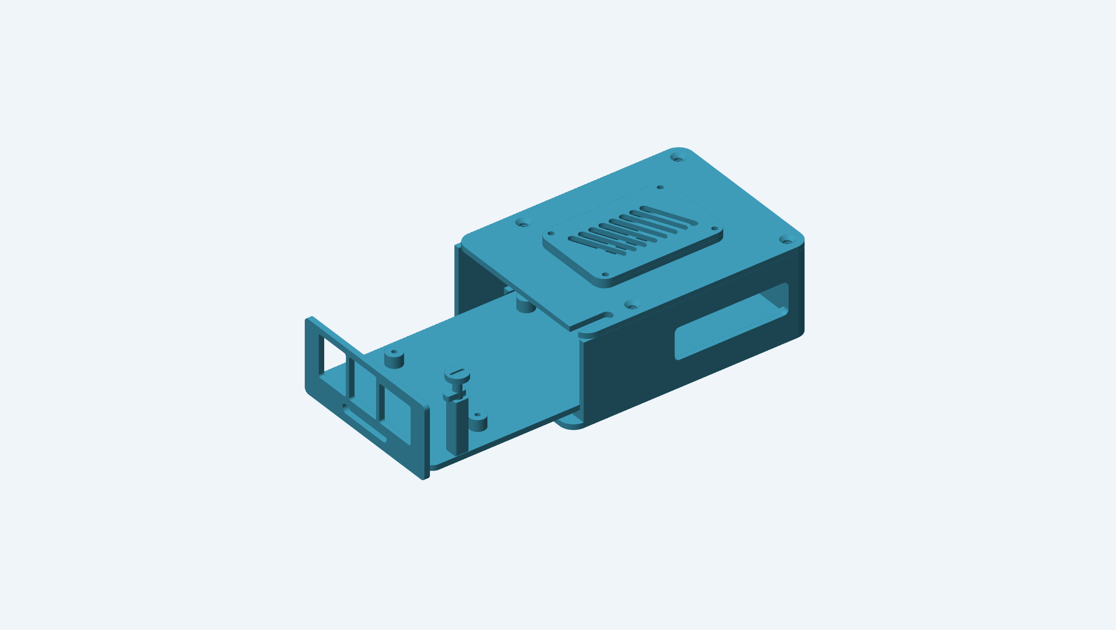
This is a modeling lesson: start with reference geometry, make parts that fit around it, give the moving parts explicit frames, and check the result before exporting it. Modeling cells use Smith's built-in renderer; inspection cells show measurements or check results. Drag to rotate, scroll to zoom, or use Fullscreen to inspect a detail. Earlier recipes remain available as we add features.
Work through the cells in order. The final cells write STEP, STL, 3MF, and SVG files beneath output/pi-enclosure in the notebook runtime's working directory. No other model files are needed.
The design has been checked computationally, but has not yet been physically printed or temperature-tested. Treat the port and cooler reference envelopes as dimensions to verify against your hardware, rather than a claim of production fit.
Before starting, work through mechanical parts, nested assemblies, and joints. Steps 1–7 build the chassis and tray; 8–13 add the duct, covers, and latch; 14–20 assemble, check, and export them. A coupon is a small test piece that lets you check a fit before printing a complete part.
1. Establish the coordinate system
Put the PCB's lower-left corner at X=0, Y=0, viewed from above. X runs along the 85 mm board toward USB/Ethernet; Y runs across its 56 mm width toward the GPIO header. Z points up. The tray withdraws along +X.
Use the official board drawing for the outline, mounting pattern, and connector centers. The Active Cooler drawing gives a 63.5 × 42.5 × 13.7 mm overall envelope. Both drawings describe approximate reference dimensions.
| Dimension | Value | Basis |
|---|---|---|
| PCB outline | 85 × 56 mm | Board drawing |
| Mounting pattern | 58 × 49 mm; first center at 3.5, 3.5 | Board drawing |
| End connector centers, Y | 10.2, 29.1, 47 mm | Board drawing |
| Side connector centers, X | 11.2, 25.8, 39.2 mm | Board drawing |
| PCB thickness | 1.6 mm | Design assumption; verify |
| Connector housing sizes and cooler placement | Simplified below | Conservative design references; verify |
| Sliding clearance | 0.4 mm per running surface | Initial printing allowance; test coupon first |
Keep dimensions distinct from numerical tolerance. A 0.4 mm mechanical gap is real space in the design. Mesh deflection only controls how the surface is approximated by triangles.
alias Smith.{Assembly, Drawing, Plane, Selector, Sketch}

p = %{wall: 2.4, gap: 0.4, tray_t: 2.4, rail_top: 5.5, standoff: 5.0, pcb_t: 1.6, body_top: 36.4}

p =
  Map.merge(p, %{
    tray_z: p.rail_top + p.gap,
    board_z: p.rail_top + p.gap + p.tray_t + p.standoff
  })

mounts = for x <- [3.5, 61.5], y <- [3.5, 52.5], do: {x, y}
lid_mounts = for x <- [-4, 64], y <- [-4, 60], do: {x, y}
vent_mounts = for x <- [16, 64], y <- [12, 44], do: {x, y}
foot_centers = for x <- [-3, 86], y <- [-3, 59], do: {x, y}

pcb =
  Sketch.rounded_rectangle(85, 56, 3,
    align: {:min, :min},
    on: Plane.xy(z: p.board_z)
  )
  |> Sketch.cut(for {x, y} <- mounts, do: Sketch.circle(1.35, at: {x, y}))
  |> Smith.extrude(p.pcb_t)

Smith.Kino.render(pcb, label: "PCB outline and mounting holes")
2. Model the reference geometry
Reference geometry must include the features that could interfere with the enclosure. The sockets below have open fronts, so the preview also makes the board's orientation easy to recognize. Their dimensions are in a table so they can be updated after measurement.
The cooler's fins and blower are simplified. The clearance check uses a separate box enclosing the cooler, including space omitted from the visible model. The envelope is placed wholly above the PCB, including the drawing's full overall height; that is conservative vertically.
end_ports = [{10.2, 17.0, 14.0}, {29.1, 15.0, 16.0}, {47.0, 15.0, 16.0}]

end_sockets =
  for {y, width, height} <- end_ports do
    Smith.box(19, width, height, at: {69, y - width / 2, p.board_z + p.pcb_t})
    |> Smith.cut(
      Smith.box(5, width - 2, height - 2, at: {84, y - width / 2 + 1, p.board_z + p.pcb_t + 1})
    )
  end

side_sockets =
  for {x, width} <- [{11.2, 9}, {25.8, 7}, {39.2, 7}] do
    Smith.box(width, 7, 3.5, at: {x - width / 2, -1.5, p.board_z + p.pcb_t})
  end

header = Smith.box(51, 5, 2, at: {7, 50, p.board_z + p.pcb_t})

pins =
  for x <- 8..27, y <- [51.3, 53.8] do
    Smith.box(0.65, 0.65, 6, at: {7 + (x - 8) * 2.54, y, p.board_z + p.pcb_t + 2})
  end

board = Smith.compound([pcb, header | end_sockets ++ side_sockets ++ pins])
cooler_z = p.board_z + p.pcb_t + 1
cooler_base = Smith.box(63.5, 42.5, 1.2, at: {0, 6.5, cooler_z})

fins =
  for x <- 7..25//3 do
    Smith.box(1, 36, 9, at: {x, 9, cooler_z + 1.2})
  end

blower =
  Smith.box(30, 30, 10, at: {27, 19, cooler_z + 1.2})
  |> Smith.cut(Smith.cylinder(13, 4, at: {42, 34, cooler_z + 8}))

cooler = Smith.compound([cooler_base, blower | fins])
cooler_envelope = Smith.box(63.5, 42.5, 13.7, at: {0, 6.5, p.board_z + p.pcb_t})
hardware = Smith.compound([board, cooler])

Smith.Kino.render(hardware, label: "Board and cooler references")
3. Hollow the chassis
Start with a rounded footprint and extrude it. Shelling removes the selected top face and moves the remaining surfaces inward. The negative thickness preserves the outside dimensions. count: 1 makes the intended opening explicit.
The second operation opens the USB/Ethernet end, leaving the floor as a short plinth below the drawer. Keep body_shell: it is a useful comparison and remains unchanged after cutting.
body_blank =
  Sketch.rounded_rectangle(106, 76, 6, align: {:min, :min}, at: {-10, -10})
  |> Smith.extrude(p.body_top)

body_shell =
  body_blank
  |> Smith.shell(openings: Selector.facing(:z), thickness: -p.wall, count: 1, join: :intersection)

body = body_shell |> Smith.cut(Smith.box(10, 80, 40, at: {90, -12, p.wall}))

Kino.Layout.grid(
  [
    Smith.Kino.render(body_shell, label: "Closed shell"),
    Smith.Kino.render(body, label: "Open end for the drawer")
  ],
  columns: 2
)
4. Add slide rails and lid mounts
The lower rails support the tray. The upper rails have triangular cross-sections: the sloping underside captures its edges and avoids a wide horizontal overhang. A sketch on the YZ plane extrudes along +X.
Model one side and mirror it across Y=28. This keeps the mating features symmetric without repeating coordinates. The upper rails stop before the latch tower, leaving its withdrawal path clear.
The lid mounts sit above the hardware envelope. Drill their pilot holes from a fixed plane; using a changing face centroid would be the wrong datum for a repeated mounting pattern.
lower_rail = Smith.box(97.6, 4, p.rail_top - p.wall, at: {-7.6, -7.6, p.wall})
tray_top = p.tray_z + p.tray_t

upper_rail =
  Sketch.polygon(
    [
      {-7.6, tray_top},
      {-4.6, tray_top + 3},
      {-7.6, tray_top + 3}
    ],
    on: Plane.yz(x: -7.6)
  )
  |> Smith.extrude(77.6)

body =
  body
  |> Smith.fuse([
    lower_rail,
    Smith.mirror(lower_rail, Plane.xz(y: 28)),
    upper_rail,
    Smith.mirror(upper_rail, Plane.xz(y: 28))
  ])

body =
  for {x, y} <- lid_mounts, reduce: body do
    chassis ->
      chassis
      |> Smith.fuse(Smith.cylinder(4, 6.6, at: {x, y, 29.8}))
      |> Smith.hole(on: Plane.xy(z: p.body_top), at: {x, y}, diameter: 2.6, depth: 6)
  end

Smith.Kino.render(body, label: "Rails and four lid mounts")
5. Cut service openings
A shared side opening gives USB-C and both micro-HDMI plugs room for their molded shoulders. Three tight holes around metal sockets would not necessarily let cables seat fully.
The rear has a vent opening and a separate microSD access slot. The curved pocket near the front is the latch keeper. A circular cut clears the cam through its whole rotation. We will check that it turns freely but blocks drawer withdrawal when locked.
A blind hole cuts along the entry plane's negative normal. These rear fastener holes use through: :all, so they span the body in either direction along X.
side_bay =
  Sketch.rounded_rectangle(50, 14, 2,
    at: {25, p.board_z + p.pcb_t + 4},
    on: Plane.xz(y: -12)
  )
  |> Smith.extrude(-7)

rear_opening =
  Sketch.rounded_rectangle(42, 14, 3,
    at: {28, 24},
    on: Plane.yz(x: -12)
  )
  |> Smith.extrude(6)

card_opening =
  Sketch.slot(16, 5,
    at: {23, 11.8},
    on: Plane.yz(x: -12)
  )
  |> Smith.extrude(6)

keeper = Smith.cylinder(5.9, 3.2, at: {76, -4, 31.1})
body = body |> Smith.cut([side_bay, rear_opening, card_opening, keeper])

body =
  for y <- [4, 52], reduce: body do
    chassis ->
      Smith.hole(chassis, on: Plane.yz(x: -10), at: {y, 24}, diameter: 2.4, through: :all)
  end

body =
  body
  |> Smith.cut(
    for {x, y} <- foot_centers,
        do: Smith.cylinder(4, 2, at: {x, y, -1})
  )

Smith.Kino.render(body, label: "Finished chassis and cable access")
6. Build the board tray
The four mounting posts use the same coordinates as the PCB. Their tops define the board's underside. A 2.1 mm pilot is an initial choice for an M2.5 screw in printed plastic; test your material and screw before fitting the board.
The tray's rear corners need more than a small edge gap: they must also clear the chassis's rounded inner corners. Use a 4 mm tray radius. Later, a Boolean intersection checks the whole shape rather than relying on matching bounding boxes.
tray_floor =
  Sketch.rounded_rectangle(97.6, 70.4, 4,
    align: {:min, :min},
    at: {-7.2, -7.2},
    on: Plane.xy(z: p.tray_z)
  )
  |> Smith.extrude(p.tray_t)

tray =
  for {x, y} <- mounts, reduce: tray_floor do
    deck ->
      deck
      |> Smith.fuse(Smith.cylinder(3.5, p.standoff, at: {x, y, tray_top}))
      |> Smith.hole(on: Plane.xy(z: p.board_z), at: {x, y}, diameter: 2.1, depth: p.standoff + 1)
  end

board_on_tray = Smith.compound([tray, board])

Kino.Layout.grid(
  [
    Smith.Kino.render(tray, label: "Tray and mounting posts"),
    Smith.Kino.render(board_on_tray, label: "Board on the tray")
  ],
  columns: 2
)
7. Add tray front panel
The front panel travels with the board, so its three large socket openings stay aligned during removal. The low horizontal slot is a finger pull. The panel and tray are fused into one printable part.
The narrow tower supports the latch shaft. Its bore stops above the tray floor; only the smaller retaining-screw hole goes through the floor. A washer under the tray prevents the screw head from pulling through. Do not tighten the retaining screw enough to clamp the cam against its bearing.
fascia =
  Sketch.rounded_rectangle(70.4, 32, 2,
    at: {28, 19.2},
    on: Plane.yz(x: 90.4)
  )
  |> Smith.extrude(2.4)

port_windows =
  for {y, width, height} <- [{10.2, 18.4, 16.8}, {29.1, 16, 18.4}, {47, 16, 18.4}] do
    Sketch.rounded_rectangle(width, height, 1,
      at: {y, 14 + height / 2},
      on: Plane.yz(x: 89.4)
    )
    |> Smith.extrude(5)
  end

pull = Sketch.slot(26, 4, at: {28, 9}, on: Plane.yz(x: 89.4)) |> Smith.extrude(5)
fascia = fascia |> Smith.cut(port_windows ++ [pull])

post =
  Smith.box(6, 6, 31 - tray_top, at: {73, -7, tray_top})
  |> Smith.fillet(edges: {:parallel, :z}, radius: 0.7, count: 4)

tray =
  tray
  |> Smith.fuse([fascia, post])
  |> Smith.cut(Smith.cylinder(2.1, 23, at: {76, -4, 9}))
  |> Smith.hole(on: Plane.xy(), at: {76, -4}, diameter: 2.4, through: :all)

Smith.Kino.render(tray, label: "Service tray, front panel, and latch bearing")
8. Loft the cooling duct
The lower end aligns with the cooler; the upper end shifts toward the lid's center and changes proportion. Three stations describe that transition. A smooth loft interpolates between them, while a ruled loft connects each pair directly.
Use an ordinary function to build the same stations with an inset. The outer and inner lofts share their heights and centers. Their profile dimensions differ by 2 mm per side. This is a section allowance, not a promise of constant normal wall thickness on a sloping surface.
The core extends beyond both ends so subtraction opens the duct completely. Loft sections themselves cannot contain holes; subtracting a second loft gives us the hollow passage.
stations = [
  {29.8, 33.6, 33.6, 42, 34},
  {34.3, 41.0, 30.8, 41, 31},
  {38.8, 48.0, 28.0, 40, 28}
]

duct_sections = fn inset ->
  for {z, width, depth, x, y} <- stations do
    Sketch.rounded_rectangle(width - 2 * inset, depth - 2 * inset, 7 - inset,
      at: {x, y},
      on: Plane.xy(z: z)
    )
  end
end

outer = Smith.loft(duct_sections.(0), ruled: false)
inner_sections = duct_sections.(2)

core =
  Smith.loft(inner_sections, ruled: false)
  |> Smith.fuse([
    Smith.extrude(hd(inner_sections), -1),
    Smith.extrude(List.last(inner_sections), 1)
  ])

duct = Smith.cut(outer, core)
ruled_envelope = Smith.loft(duct_sections.(0))

Kino.Layout.grid(
  [
    Smith.Kino.render(ruled_envelope, label: "Ruled envelope"),
    Smith.Kino.render(duct, label: "Hollow smooth loft")
  ],
  columns: 2
)
9. Add the flange and inspect a section
The flange rests on the lid. Four screws clamp the grille, flange, and lid together; the duct does not attach to the cooler or prevent tray removal.
A section makes the inner passage visible. section/2 returns filled faces suitable for area queries or another extrusion. Here we give the section 0.5 mm thickness only to make its wall bands easy to inspect in 3D. That thin slice is a diagnostic model and will not be exported as a part.
flange =
  Sketch.rounded_rectangle(56, 38, 5, at: {40, 28}, on: Plane.xy(z: 38.8))
  |> Sketch.cut(Sketch.rounded_rectangle(44, 24, 5, at: {40, 28}))
  |> Smith.extrude(2)

duct = duct |> Smith.fuse(flange)

duct =
  for {x, y} <- vent_mounts, reduce: duct do
    part -> Smith.hole(part, on: Plane.xy(z: 40.8), at: {x, y}, diameter: 2.4, through: :all)
  end

duct_slice = duct |> Smith.section(Plane.xz(y: 34)) |> Smith.extrude({0, -0.5, 0})

Kino.Layout.grid(
  [
    Smith.Kino.render(duct, label: "Duct and mounting flange"),
    Smith.Kino.render(duct_slice, label: "Section through the passage")
  ],
  columns: 2
)
10. Derive the lid opening from the duct
A rectangular opening sized only at the outlet can collide with the curved duct farther down. Reuse the loft stations with a negative inset to make a clearance tool, then subtract that tool from the lid.
The open-ended slot near the front lets the latch shaft travel with the tray. Countersinks keep the four chassis screws flush with the lid.
clearance_sections = duct_sections.(-0.4)

duct_clearance =
  Smith.loft(clearance_sections, ruled: false)
  |> Smith.fuse(Smith.extrude(List.last(clearance_sections), 3))

lid =
  Sketch.rounded_rectangle(100, 76, 6, at: {40, 28}, on: Plane.xy(z: p.body_top))
  |> Smith.extrude(p.wall)
  |> Smith.cut(duct_clearance)
  |> Smith.cut(Sketch.slot(20, 4.4, at: {83, -4}, on: Plane.xy(z: 35)) |> Smith.extrude(6))

lid =
  for {x, y} <- lid_mounts, reduce: lid do
    cover ->
      Smith.countersink(cover,
        on: Plane.xy(z: 38.8),
        at: {x, y},
        diameter: 3.2,
        sink_diameter: 6,
        angle: 90,
        through: :all
      )
  end

lid =
  for {x, y} <- vent_mounts, reduce: lid do
    cover -> Smith.hole(cover, on: Plane.xy(z: 38.8), at: {x, y}, diameter: 2.4, through: :all)
  end

Smith.Kino.render(lid, label: "Lid with a fitted duct opening and service slot")
11. Design a replaceable grille
The grille's perimeter and mounting holes form its interface. The slots are a separate feature function. Keeping those separate lets us compare patterns without changing the parts that mate with it.
Build each slot around the origin, rotate it, then translate it into position. Reversing that order would rotate the translation too. The two variants below use the same blank and fastener pattern; only the slant changes.
grille_blank =
  Sketch.rounded_rectangle(56, 38, 5, at: {40, 28}, on: Plane.xy(z: 40.8))
  |> Smith.extrude(2)

vent_slots = fn angle ->
  for i <- 0..7 do
    Sketch.slot(23, 3.2)
    |> Smith.extrude(4)
    |> Smith.rotate({0, 0, 1}, angle)
    |> Smith.translate({40 + (i - 3.5) * 4.5, 28, 39.8})
  end
end

make_grille = fn angle ->
  perforated = grille_blank |> Smith.cut(vent_slots.(angle))

  for {x, y} <- vent_mounts, reduce: perforated do
    panel -> Smith.hole(panel, on: Plane.xy(z: 42.8), at: {x, y}, diameter: 2.4, through: :all)
  end
end

grille = make_grille.(65)
grille_alternate = make_grille.(115)

Kino.Layout.grid(
  [
    Smith.Kino.render(grille, label: "Forward slant"),
    Smith.Kino.render(grille_alternate, label: "Reverse slant")
  ],
  columns: 2
)
12. Complete the rear vent and feet
The rear grille bolts over its opening. Its slots run vertically in the YZ plane; the 90-degree rotation is about world X. The shorter horizontal slot below it remains available for the microSD card.
Each foot fits a shallow recess in the chassis underside. The printed foot is sized for a small adhesive gap. Use TPU or substitute suitably sized rubber feet if grip matters.
rear_grille =
  Sketch.rounded_rectangle(54, 20, 3,
    at: {28, 24},
    on: Plane.yz(x: -12)
  )
  |> Smith.extrude(2)

rear_slots =
  for y <- [12, 20, 28, 36, 44] do
    Sketch.slot(12, 3, on: Plane.yz(x: -13))
    |> Smith.extrude(4)
    |> Smith.rotate({1, 0, 0}, 90)
    |> Smith.translate({0, y, 24})
  end

rear_grille = rear_grille |> Smith.cut(rear_slots)

rear_grille =
  for y <- [4, 52], reduce: rear_grille do
    panel -> Smith.hole(panel, on: Plane.yz(x: -12), at: {y, 24}, diameter: 2.4, through: :all)
  end

foot = Smith.cylinder(3.8, 2.8, at: {0, 0, -2})

Kino.Layout.grid(
  [
    Smith.Kino.render(rear_grille, label: "Rear grille"),
    Smith.Kino.render(foot, label: "Recessed foot")
  ],
  columns: 2
)
13. Make the quarter-turn cam
Build the cam around its own Z axis. The assembly will place that axis at X=76, Y=-4. At zero degrees, the tab points along +X and clears the side wall. At −90 degrees it enters the keeper pocket.
The cam, shaft, and knob are one part. A small blind pilot opens from the shaft's underside for its retaining screw. The knob has a screwdriver slot; the direction of that slot also makes the pose visible. The cam has 0.5 mm axial clearance over the tower and 0.3 mm radial clearance in its bore.
cam =
  Sketch.rounded_rectangle(8.5, 3.4, 1, at: {1.25, 0}, on: Plane.xy(z: 31.5))
  |> Smith.extrude(2.4)
  |> Smith.fuse([
    Smith.cylinder(1.8, 10.2, at: {0, 0, 29}),
    Smith.cylinder(4.5, 2.4, at: {0, 0, 39.2})
  ])
  |> Smith.cut(Sketch.slot(6, 1.2, on: Plane.xy(z: 40.8)) |> Smith.extrude(2))
  |> Smith.hole(on: Plane.new(origin: {0, 0, 29}, normal: {0, 0, -1}), diameter: 1.6, depth: 7)

Smith.Kino.render(cam, label: "Cam, shaft, and thumb knob")
14. Assemble the service cartridge
A nested assembly keeps the tray, latch, board, and cooler together. Hardware is reference geometry: it follows the cartridge but does not enter the print pack.
The bearing and shaft frames use their parts' original coordinates. Connecting them overrides the cam's initial placement. Start each pose from the same unconnected cartridge; a second connection on the same moving member would not replace the first.
cartridge =
  Assembly.new(:cartridge)
  |> Assembly.part(:tray, tray, print: [on_bed: true])
  |> Assembly.part(:cam, cam, print: [on_bed: true], exploded_offset: {0, 0, 18})
  |> Assembly.reference(:board, board)
  |> Assembly.reference(:cooler, cooler)
  |> Assembly.joint(:bearing, on: :tray, at: Plane.xy(origin: {76, -4, 31.5}))
  |> Assembly.joint(:shaft, on: :cam, at: Plane.xy(z: 31.5))

pose_cartridge = fn angle ->
  Assembly.connect(cartridge, :shaft,
    to: :bearing,
    kind: :revolute,
    angle: angle,
    limits: [angle: {-90, 0}]
  )
end

{:ok, cartridge_result} = pose_cartridge.(-90) |> Smith.evaluate()

Smith.Kino.render(cartridge_result, label: "Tray with the cam locked")
15. Define the drawer motion
A second assembly owns the chassis, covers, and service cartridge. Both slide frames have their normal along +X, so the linear joint's offset is the withdrawal distance.
The geometric joint does not enforce the physical latch. The enclosure function makes the intended operating sequence explicit: only an unlocked cam may withdraw. We will independently check the cam's physical blocking action in the next section.
The feet are repeated instances of one recipe. Part names remain stable, even when a dimension or pose changes.
enclosure = fn travel, angle ->
  if travel > 0 and angle != 0,
    do: raise(ArgumentError, "Unlock the cam before withdrawing the tray")

  frame = Plane.new(normal: {1, 0, 0}, x_direction: {0, 1, 0})

  fixed =
    Assembly.new(:pi_enclosure)
    |> Assembly.part(:chassis, body, print: [on_bed: true])
    |> Assembly.part(:lid, lid,
      print: [rotation: {{1, 0, 0}, 180}, on_bed: true],
      exploded_offset: {0, 0, 35}
    )
    |> Assembly.part(:duct, duct,
      print: [rotation: {{1, 0, 0}, 180}, on_bed: true],
      exploded_offset: {0, 0, 55}
    )
    |> Assembly.part(:grille, grille, print: [on_bed: true], exploded_offset: {0, 0, 65})
    |> Assembly.part(:rear_grille, rear_grille,
      print: [rotation: {{0, 1, 0}, -90}, on_bed: true],
      exploded_offset: {-15, 0, 0}
    )
    |> Assembly.subassembly(:cartridge, pose_cartridge.(angle), exploded_offset: {45, 0, 0})

  fixed =
    for {{x, y}, index} <- Enum.with_index(foot_centers, 1), reduce: fixed do
      assembly ->
        Assembly.part(assembly, "foot-#{index}", foot,
          position: {x, y, 0},
          print: [on_bed: true],
          exploded_offset: {0, 0, -8}
        )
    end

  fixed
  |> Assembly.joint(:guide, on: :chassis, at: frame)
  |> Assembly.joint(:slider, on: :cartridge, at: frame)
  |> Assembly.connect(:slider,
    to: :guide,
    kind: :linear,
    offset: travel,
    limits: [offset: {0, 105}]
  )
end

{:ok, closed} = enclosure.(0, -90) |> Smith.evaluate()
{:ok, open} = enclosure.(65, 0) |> Smith.evaluate()
{:ok, open_board} = Assembly.fetch(open, [:cartridge, :board])

Kino.Layout.grid(
  [
    Smith.Kino.render(closed, label: "Closed and locked"),
    Smith.Kino.render(open, label: "Unlocked, tray withdrawn 65 mm"),
    Smith.Kino.render(open_board, label: "Board follows the cartridge")
  ],
  columns: 1
)
16. Check clearances and latch engagement
Use named inspection reports for the fixed interfaces. The clearance check measures material distance and interference volume. Contact is allowed here, but overlap above the stated volume tolerance is a failure. For the many travel samples, a small native helper checks only overlap volume, which is the requirement at hand.
Evaluate fixed geometry once. For the travel checks, translate the evaluated moving shape directly through OCEx. That avoids rebuilding all of its feature history at each sample. These are checks at discrete positions, not continuous collision detection.
overlap = fn a, b ->
  {:ok, intersection} = OCEx.common(a, b)
  {:ok, volume} = OCEx.volume(intersection)
  volume
end

{:ok, body_result} = Smith.evaluate(body)
{:ok, lid_result} = Smith.evaluate(lid)
{:ok, duct_result} = Smith.evaluate(duct)
{:ok, tray_result} = Smith.evaluate(tray)
{:ok, board_result} = Smith.evaluate(board)
{:ok, envelope_result} = Smith.evaluate(cooler_envelope)
{:ok, locked_cam} = Assembly.fetch(closed, [:cartridge, :cam])
{:ok, unlocked_cartridge} = pose_cartridge.(0) |> Smith.evaluate()
{:ok, unlocked_cam} = Assembly.fetch(unlocked_cartridge, :cam)

{:ok, moving} =
  OCEx.compound([
    tray_result.shape,
    unlocked_cam.shape,
    board_result.shape,
    envelope_result.shape
  ])

{:ok, fixed} = OCEx.compound([body_result.shape, lid_result.shape, duct_result.shape])

fit_checks = [
  {"Tray / chassis", tray_result.shape, body_result.shape},
  {"Board / tray", board_result.shape, tray_result.shape},
  {"Cooler envelope / covers", envelope_result.shape, fixed},
  {"Duct / lid", duct_result.shape, lid_result.shape},
  {"Locked cam / chassis", locked_cam.shape, body_result.shape}
]

fit_rows =
  for {name, a, b} <- fit_checks do
    {:ok, report} = Smith.Inspection.run(%{moving: a, fixed: b}, checks: [
      {:clearance, :moving, :fixed, minimum: 0, tolerance: 1.0e-7, volume_tolerance: 1.0e-5}
    ])
    :passed = report.status
    [check] = report.checks
    %{check: name, overlap_mm3: Float.round(check.interference_mm3, 8)}
  end

travel_rows =
  for distance <- 0..105//5 do
    {:ok, position} = OCEx.translate(moving, {distance, 0, 0})
    volume = overlap.(fixed, position)
    if volume >= 1.0e-5, do: raise("Interference at #{distance} mm travel: #{volume} mm³")
    %{check: "Travel #{distance} mm", overlap_mm3: Float.round(volume, 8)}
  end

{:ok, attempted_pull} = OCEx.translate(locked_cam.shape, {2, 0, 0})
true = overlap.(body_result.shape, attempted_pull) > 0.1

Kino.DataTable.new(fit_rows ++ travel_rows)
The last assertion is intentionally different: moving the locked cam 2 mm must intersect the keeper. That establishes a physical stop, separately from the pose function's guard.
Now check intermediate latch angles while the drawer is seated, and compare vent free area with a reference inlet circle. Free area is useful geometry, but it does not predict pressure drop, fan noise, or cooling performance. The rear grille is an exhaust opening, not a sealed return duct.
for angle <- -90..0//15 do
  {:ok, pose} = pose_cartridge.(angle) |> Smith.evaluate()
  {:ok, placed_cam} = Assembly.fetch(pose, :cam)

  for fixed_shape <- [body_result.shape, lid_result.shape, tray_result.shape] do
    true = overlap.(fixed_shape, placed_cam.shape) < 1.0e-5
  end
end

slot_area = 8 * ((23 - 3.2) * 3.2 + :math.pi() * :math.pow(3.2 / 2, 2))
reference_inlet_area = :math.pi() * 13 * 13
true = slot_area > reference_inlet_area
cooler_clearance = 29.8 - (p.board_z + p.pcb_t + 13.7)
true = cooler_clearance >= 1.0

Kino.DataTable.new([
  %{measurement: "Top grille free area", value: Float.round(slot_area, 2), units: "mm²"},
  %{
    measurement: "26 mm reference inlet",
    value: Float.round(reference_inlet_area, 2),
    units: "mm²"
  },
  %{
    measurement: "Vertical cooler clearance",
    value: Float.round(cooler_clearance, 2),
    units: "mm"
  }
])
17. Make a fit coupon from the actual mating parts
Before printing a whole chassis, print a short rail section and the matching tray edge. Intersecting the real recipes preserves the geometry being tested; a hand-drawn approximation could accidentally test a different fit.
These are separate parts that print in their operating orientation. Test sliding and capture after normal cleanup. If you change the fit, update both the mating dimensions and the checks, then rerun the notebook. The current coupon records the 0.4 mm design, not a universal printer tolerance.
rail_coupon = body_result |> Smith.from_result() |> Smith.common(Smith.box(16, 14, 14, at: {-2, -12, 0}))
tray_coupon = tray_result |> Smith.from_result() |> Smith.common(Smith.box(16, 8, 10, at: {-2, -7.5, 3}))

coupons =
  Assembly.new(:rail_fit)
  |> Assembly.part(:rail, rail_coupon, print: [on_bed: true])
  |> Assembly.part(:tongue, tray_coupon, print: [on_bed: true], exploded_offset: {0, 0, 12})

{:ok, coupon_result} = Smith.evaluate(coupons)
{:ok, exploded_coupons} = Assembly.view(coupon_result, :exploded)

Kino.Layout.grid(
  [
    Smith.Kino.render(coupon_result, label: "Rail coupon in operating position"),
    Smith.Kino.render(exploded_coupons,
      label: "Print these two pieces first"
    )
  ],
  columns: 2
)
18. Preview the exploded assembly
Exploded offsets are presentation metadata. Applying them produces a separate result; it does not change the installed assembly or the print placements. Notice that the cartridge moves as a group and its cam also has a local exploded offset.
References stay out of the manufactured assembly preview. Fetch them explicitly when you want to inspect hardware, as we did for the board.
{:ok, exploded} = Assembly.view(closed, :exploded)
Smith.Kino.render(exploded, label: "Enclosure, covers, service cartridge, and feet")
19. Create assembly drawings
The 3D preview is useful for inspecting form. A drawing makes port layout and hidden features easier to compare. These views come from the evaluated tray, so there is no second outline to keep synchronized.
The YZ view looks along −X toward the socket panel. Hidden lines are dashed. Add a measured tray length to the top view. The label comes from the evaluated part and stays tied to that revision; this does not create a full manufacturing sheet or specify tolerances for every feature.
{:ok, tray_top_drawing} = Drawing.new(tray_result, on: :xy)
{:ok, tray_front_drawing} = Drawing.new(tray_result, on: :yz)
{:ok, tray_length} = Smith.Measure.extent(tray_result, :x)
{:ok, tray_top_drawing} = Drawing.dimension(tray_top_drawing, tray_length,
  orientation: :horizontal, offset: -10)
{:ok, top_svg} = Drawing.svg(tray_top_drawing, title: "Tray · Top")
{:ok, front_svg} = Drawing.svg(tray_front_drawing, title: "Tray · Socket panel")
Kino.Layout.grid([Smith.Kino.render(tray_top_drawing, label: "Tray · Top"),
  Smith.Kino.render(tray_front_drawing, label: "Tray · Socket panel")], columns: 1)
20. Export printable parts
Export the installed assembly. Smith applies each part's print placement to STL and 3MF while retaining installed placement in the assembly STEP. The board and cooler remain references and cannot enter the print pack.
The lid and duct turn upside down for printing; the rear grille turns onto its flat back. Those are starting orientations. Inspect bridges around the tray's port openings, the cam's overhangs, and the duct's slope in your slicer; enable supports where your process needs them. STL and 3MF contain geometry, not slicer settings.
The export checks mesh connectivity and volume agreement, and reads STEP back for verification. It does not certify physical fit or thermal performance.
output = Path.expand("output/pi-enclosure")

{:ok, files} =
  Smith.export(closed, output,
    name: "pi-enclosure",
    tolerance: 0.02,
    angular_tolerance: 0.1,
    metadata: %{
      hardware: "Raspberry Pi 5 + Active Cooler",
      physical_validation: "prototype pending"
    }
  )

{:ok, coupon_files} =
  Smith.export(coupon_result, Path.join(output, "fit-test"),
    name: "rail-fit",
    tolerance: 0.02,
    angular_tolerance: 0.1
  )

{:ok, print_pack} = :zip.extract(File.read!(files.print_pack), [:memory])
true = length(print_pack) == 2 * length(files.parts)
true = Enum.all?(files.parts, & &1.verification.mesh.watertight)
true = Enum.all?(files.parts, & &1.verification.mesh.winding_consistent)

# Keep drawings beside the particular export they document.
drawings_dir = Path.join(Path.dirname(files.assembly_step), "drawings")
File.mkdir_p!(drawings_dir)
{:ok, _} = Drawing.write(tray_top_drawing, Path.join(drawings_dir, "tray-top.svg"))
{:ok, _} = Drawing.write(tray_front_drawing, Path.join(drawings_dir, "tray-front.dxf"))

Kino.DataTable.new([
  %{output: "All printable STL/3MF pairs", path: files.print_pack},
  %{output: "Installed assembly STEP", path: files.assembly_step},
  %{output: "Board and cooler references", path: files.references_step},
  %{output: "Rail fit-test pack", path: coupon_files.print_pack},
  %{output: "Tray drawings", path: drawings_dir}
])
Assemble and test the prototype
Start with the rail coupon and a screw-pilot test in the intended material. Check the PCB, cooler, and cable envelopes against the physical hardware before committing to the full print.
| Hardware | Starting specification | Purpose |
|---|---|---|
| 4 screws | M2.5 × 6 mm | Board to tray; printed pilots need a fit test |
| 4 screws | M3 × 8 mm, countersunk | Lid to chassis; verify head profile and pilot fit |
| 4 screws and nuts | M2 × 10 mm | Top grille, duct flange, and lid |
| 2 screws and nuts | M2 × 8 mm | Rear grille |
| 1 screw and washer | M2 × 30 mm | Cam retention from below the tray; adjust length/washer stack for free rotation |
| 4 feet | Printed TPU or suitably sized rubber | Grip and separation from the desk |
Fit the board with the Active Cooler already installed. Check screw engagement without letting tips reach the PCB. Fit the cam and its retaining screw, then confirm it rotates freely. Slide in the tray, fit the rear grille and lid assembly, and turn the cam into the keeper. Unplug cables before withdrawing the tray.
Check that every plug seats fully, the microSD card is accessible, the fan turns freely, and the drawer withdraws without touching the cooler or covers. Run the same workload with the lid off and on and compare temperatures and noise. The top duct guides inlet air; its actual effect on cooling has not been measured.
Explore the design
- Change the grille slant from 65° to 115°. Its interface stays fixed; inspect both variants before choosing one.
- Change a duct station's center or size, then rerun the lid-clearance and hardware checks. Watch how a local profile change affects another part.
- Make a thinner rail coupon by shortening only its intersection tool. The mating profile should remain identical.
- Increase the cooler envelope height until the cover check fails. Find the interfering part, then decide whether to raise the lid or change the duct.


